Wednesday, February 1, 2012

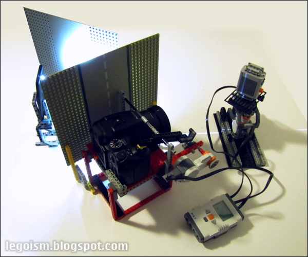
Experiment: 3D scanner with white planar illumination

3D-Scanner-NXT

Beam & spin 3D scanners are not particularly new: there is plenty of such projects both beyond and within the Legosphere, among which the one built by Philippe "Philo" Hurbain is an excellent example if you are considering developing one. Regardless of their wide variations, they follow the same operating principle ― they aim a planar laser at the scanned object, and record (or photograph) the resulting contours as the object is rotated. With a bit of picture processing, math and geometry, a digital 3D model can be assembled. Accuracy depends on laser sharpness, camera perspective, precision of the rotating mechanism and a couple of other factors, but can yield suprisingly high resolution.

Two obvious problems of these scanners are their inability to scan the object's surface colours, and the reliance on a rather rare component: a planar laser is not something likely to wait readily in your old toy box. There are ways to improvise with usual laser pointers, though it complicates matters again.

3D-Scanning-Sequence I've tried to work around these problems by using a different type of planar illumination ― white (to allow colour scanning) and using more common hardware. After a few tries, I've settled with a flash white LED from a mobile phone, mounted behind two barriers with a narrow slot between them. This sort of LED works well since it's white, very bright and a particularly small light source ― thus reducing the undesired penumbra on the target object. The rest is just a bit of NXT at its simplest: a motorized turntable that can also slide horizontally (to scan various surfaces from several directions if needed), and a camera cradle with a triggering mechanism.

The results, as you can see on a photo of a demo sequence, are acceptable, though I have yet to write a script that will analyse the photo sequence and build a digital 3D model (probably defined by colour voxels). One can notice from the sequence photos that, while some dimensional precision is lost in comparison to laser-based scanners, the projections are clear and bright enough to be easily recognized, and colour information extracted from them. One possible problem is scanning black or at least partially black object, where there may be insufficient light to track the object shape accurately. Of course, multi-scanning with several camera positions and orientations of the target object could improve dimensional precision and perhaps colour definition too, although at a large time cost.

However, I won't go that far yet since this was intended just as a little side-experiment, initiated by a task at my day job where I needed to get exact 3D measurements of some computer components.

Tuesday, January 24, 2012

Legoism's first birthday

1st-e

Exactly one year ago, a first post (an introductory one) was posted on Legoism. I'm glad to see that the number of its page views has been continuously climbing month by month though it's, of course, still light-years away from some more established Technic blogs (many of which you can find in the Links section). I will, as the picture above suggests, try to improve it in the future.

A few numbers: the blog is now close to reaching the 25,000th page view (should be reached in about a week or so). The post with by far the most views, over 5000, is a review of 8070 Super Car ― it has roughly as much as the next four: all being reviews, from 5893, over 8053 and 8258, to 8051. It's a bit depressing that the next two posts are actually documenting two failures: the horrible Technic Supercar, and the unsuccessful NXT plotter, and only then the TGB Car. That's something I obviously need to work on. Interestingly, lots of visitors actually come to this site via image search.

Thank you everyone for visiting and reading Legoism so far ― I'll try to come up with lots of exciting stuff in the future!

Sunday, January 22, 2012

Drive configurations comparison

After a few previous posts regarding differential drive chassis and its self-steering developments, it might be useful, before we move on, to offer a table comparing all these drive configurations ― their pros and cons. Here we'll restrict the table to 4-wheeled types, though general ideas also apply to those with three or more pairs of wheels. Click on the table to zoom it for easier viewing.


Or use this thumbnail link to obtain a printer-friendly version.

legoism-chassis-comparison-pf

Sunday, January 15, 2012

Beginners' guide: One motor, many functions


Experienced builders are well acquainted with many ways to reduce several functions to a single control axle, but the concept is important enough to present it to Technic beginners. Namely, typical approach, which works just fine for majority of MOCs, uses one control axle (or a motor) for each function. However, mobile and remotely controlled models often set strict limits on the number of electric components one can use, and in such situations it is necessary to go for alternate solutions - among which this differential-ratchet-gearbox system is just one of possibilities.

A careful look at the photos should reveal at least a little bit of how this system works ― but let's describe it component by component anyway. The input axle, in this case attached directly to a motor (A) is directly linked to a differential (B) master gear. Each of its two outputs leads to ratchets (C) that limit the rotation in different directions. This twin-ratchet setup ensures that the different directions the input axle is rotated are split among two exiting axles; this can itself be a useful component.

One output axle drives the input of a simple gearbox (D) which, in this case, has three output gears, though designs with four or more shouldn't present a problem. However, there is only one sliding intermediate gear, ensuring that the input rotation can be linked to only one output axle (E) simultaneously. Of course, the other axle from the differential controls the movement of this gear. In this case, it is done with a simple worm gear, spur gear and an off-center set control beam (F).

TopRight In other words, driving the motor in one direction changes the active output axle of the gearbox in the 1-2-3-2-1 order. Running it in the other direction transfers its motion to the selected active axle. Of course, the entire system can be built more compact in practice ― this display version was designed to avoid the components being obfuscated.

Bottom There are drawbacks one needs to be aware of, of course ― most importantly, the output axles rotate in one direction only (though, if they control a linear motion, the aforementioned off-center set beam connections can help). This system also allows the unlinked axles to rotate freely in one direction, and introduces some friction (thus reducing available torque). It's too large to cram comfortably in smaller models, and finally, it's somewhat noisy. But in certain situations, the benefit of controlling everything with just a single input axle, i.e. one motor, easily overshadows these remarks.

Venturing a little further into theory, it is conceivable to attach each of the output axles to off-center linkages that control Power Function switches connected to the motors attached to further such systems, squaring the number of available output functions (output axles). However, such system would be incredibly cumbersome to use.

Finally, a few auxiliary photos without labels, and a video:

TopLeftE TopRightEBottomE

DisAsmb


Friday, January 6, 2012

Self-steering car chassis, Mark II

Opener

Some may remember a very simple self-steering chassis I've tested last February. It was about time to advance it, so here's a new self-steering chassis concept, Mark II.

Let's just quickly remind ourselves what the self-steering chassis is about, and when would one prefer it over typical designs. Namely, if a planned vehicle is limited to using only two motors altogether (due to weight, power requirements, size, simplicity or any other reason), a conventional approach would use one to provide drive, and the other to steer. However, for some particular models it might be troublesome to use only half the available power for providing drive.

Otherside An alternative is to have both motors provide drive, one for each wheel. In such configuration, steering is done by having the two motors (and of course, their respective wheels) turn at different speeds, thus producing sufficient tangential force for the chassis to turn. This type of drive, often known as a differential drive, is used by tanks, for example. However, if the chassis is wheeled, it will turn too ― at least if the front wheels have sufficient caster to readily follow it, what was the point of the aforementioned Mark I chassis. But it still suffers from poor reliability unless perfectly balanced and having minimal friction, both of which are sometimes unavoidable. Therefore, an obvious direction for improvement is to introduce a steering control that follows the drive wheels' behaviour.

Mark II concept attempts to solve this problem mechanically. To explain its functioning, let's split it down to a few main components.

Scheme Each of the rear wheels' axles (A) is linked to a differential several studs ahead (B). As you have perhaps noticed, there are three gears (C) on one, and four at the other side, resulting in one of the axles spinning in reverse. The differential thus works opposite from its typical application on the half-axle: it actually turns only when the rear wheels aren't turning at the same speeds (i.e. they tend to steer), and its rotation speed is proportional to the difference between the rear wheels' speeds. But as long as the rear wheels turn simultaneously, it remains stationary.

In other words, its turning speed is proportional to the amount of steering that needs to be done by the front wheels ― of course, also obeying the direction. But since it's the speed and not the absolute displacement we're interested in, this differential cannot be directly linked to the steering pinion. Instead, we need a simple sort of a mechanical tachometer, and that is approximately what the front differential (D) does. It has got a very light brake (E) at its main axis, and its second axle leads to a usual steering rack&pinion mechanism (F).

The point is that the brake and the rack&pinion work in balance: the more torque and speed arrive from the rear differential, the more will they be met by the increasing resistance of the brake, thus directing more towards the steering. The steering, of course, imparts its own resistance depending on how sharp turn it's attempting to make, and yet more if it's equipped with a recentering system (G). Exact steering would need a very precise balance between these variables, but in practice it needs no more than a nudge in the correct direction, and then the friction to the ground keeps it in correct geometry. In other words ― it works.

Scheme-EditedWhen there is no need to steer anymore (the rear wheels begin turning at the same speed), the rear differential will stop turning, and it will be easier for the front wheels to recenter themselves thanks to a bit of caster. Unless the weight on the front axle is huge and the tyres grippy, this force will be very light ― and that is the main reason why the pinion couldn't be linked to the rear differential through a standard clutch gear: its resistance would almost always be too high, and prevent the front wheels from recentering. Very heavy models may still get away with it, though ― but they rarely have limits on the number of motors anyway. The better but more complex solution is to introduce a recentering mechanism and adjust its force carefully according to the rest of the system, in which case the caster is not necessary.

There are still some particular situations in which Mark II works poorly, such as turning in place (with rear wheels turning in opposite directions), turning slowly in sharp curves, and driving backwards if the steering is centered only by caster (without recentering mechanisms). However, in typical circumstances it works all right.

Friday, December 16, 2011

Flashback: 8865 Test Car

Main
When talking about classic Technic supercars, it's the 8880 which (rightly) usually gets the largest spotlight. However, its predecessor, the 8865 Test Car, was just as advanced and innovative for its time. The one I've built doesn't adhere entirely to the original's colours (some original parts got damaged in those 20+ years), but mechanically it's accurate.

This set was released in 1988 ― of course, deeply in the era of studded beams and brittle toothed connectors. It relies on so many standard parts that it should be fairly simple to build if you've got a good "general" collection of studded Technic, and some special parts such as the front suspension hubs and the old differential can be replaced by their modern equivalents fairly easily. Altogether it's still visibly simpler than the 8880, but curiously, it's a tiny bit longer, wider and higher.

RearLeftBesides the part assortment, one noticeable difference to the modern Technic sets are the instructions. At 892 parts and featuring many complex systems, modern instructions for the 8865 would be spread into two or even three booklets, while the original's consist of just one booklet which isn't too thick (and shares space with the B model). The fact, provable also through other Technic sets from the time, is that the building steps were much more condensed back then, introducing many sub-steps and handling several components simultaneously. Often requiring very careful inspection of drawings to notice the changes.

The features and functionalities the Test Car offers clearly overshadow its own predecessor, the 8860. It has a V4 engine (the first Technic engine with a V layout), built from old large square pistons and using the offset axle holes in the 24T gears to form a crankshaft. It is connected to a linear axle-sliding gearbox with 3 speeds and neutral, which leads to the differential at the back.

Front independent suspension utilizes special parts relying on ball joints to allow steering, and follows the Ackermann geometry. It is based on usual rack & pinion mechanism, linked to the steering wheel in the cabin. The rear double wishbone suspension doesn't use special parts as an "easy way out", but is instead built from standard parts ― mostly beams, pins and plates, with hinge points precisely adjusted with the U-joints' fulcrums. This structure is quite wide, and together with the need to fit the differential on the same axle, it defines the car total width.

FrontRightHeadlights can be also extended and retracted using a lever in the cabin. The lever rotates a simple crank that raises or lowers the (purely decorative) lights. Finally, almost everything can be adjusted regarding the seats: the back and headrest angle with standard hinges, and the front-back position via rack & pinion.
The bodywork composed mainly of 16L and 12L beams is quite basic, especially in comparison to the modern-age Technic models, but it gives a fairly good idea of the overall outline of the car. It's rather sturdy and, together with a strong chassis, makes the 8865 one seriously shockproof model.

Along the lines of the deep-studded era Technic, there's no real static decoration here. As mentioned, even the headlights are moveable, and the engine fan rotates together with the crankshaft.

However, the model isn't entirely flawless. Changing gears is difficult, and usually impossible if the car is static (it was the later 8880 which introduced a smooth synchronized gearbox with dog-rings). The friction of the parts causes quite a strain on the parts in the first gear if extreme caution was not given to allowing slack in the transmission and suspension, or if the engine crankshaft it offset by the tiniest amount.

But altogether, 8865 is undoubtedly among the all-time Technic flagships. It is also a good demo of how much is possible using mostly regular Technic parts and a few well-known mechanisms.

GALLERY
D_Back D_Bottom D_Front D_Side
Gearbox Headlights Engine

GENESIS (Timelapse)

Wednesday, November 9, 2011

Classic Space: 6819 Orbital Shuttle

6819_Orbital_Shuttle_1000Don't bother looking for this one in the official catalogues; it's just a mockup, a graphical exercise of recreating the original Classic Space box arts (which I adore) as accurately as possible. The set number is fake, too ― among many other 68xx sets from the theme, the '19' is missing for some reason.

I've tried to keep the Shuttle more or less within the boundaries set by the Classic Space: blue hull, grey machinery, black and transparent yellow details, very simple and clean form-following-function design, and a prominently displayed Space logo both on the minifig and the craft. It's made of 55 parts, not counting the minifig.

The rest is straightforward. Spaceships are usually photographed from the starboard side at an angle and from slightly above, set against a starry background and above a beige planet surface ― tasks which any half-decent bitmap editing program can do with ease, and the background resources are found in abundance on the Internet.

Though the Classic Space is my favourite of all the Legoland/System themes, I like the Space Police Gen I too, and hope to come up with something interesting from that theme as well ― at least when the 6886 Galactic Peace Keeper arrives via Bricklink, which should provide some useful theme-specific parts.